This section describes how a raster or curve character can be modified.
This can either be done by using the toolkit with the mouse,
without having to choose a menu command first,
or by choosing an Adjust,
Transform, Metrics,
Special, or Sub-Character command.
These are described below.
All the following operations are aborted by depressing the
right mouse button during the painting process.
The character gets restored to its original shape before the operation.
The current raster character can be modified without a menu command by
painting into it with the mouse.
Select the Pencil Tool from the toolbox.
Free hand painting is then initiated by depressing the left mouse button.
Painting continues while by dragging the mouse with
the left mouse button depressed.
Normally, a one-pixel pen is used for painting.
A different pen can be loaded from the pens menu.
More about painting with pens appears in the section on
Painting with Pens.
To erase pixels in the current character use the
Eraser Tool in the toolbox.
Free hand erasing is then initiated by depressing the left mouse button.
Erasing continues while by dragging the mouse with
the left mouse button depressed.
Normally, a one-pixel pen is used for erasing.
A different pen for erasing can be loaded from the pens menu.
More about painting with pens appears in the section on
Painting with Pens.
To paint a straight line with the current pen,
select the Line Pencil Tool.
Straight line painting is then performed from the point
at which the left mouse button is depressed to the point where it gets
released.
More about pens appears in the section on Painting with Pens.
To pull a black rectangle out of its center,
use the Center Rectangle Tool from the toolbox.
Depressing the left mouse button describes the center, and releasing it
places the corner. An input panel pops now up.
There, a new center can be defined by changing the values of
Center X or Center Y,
the width or height of the rectangle can be changed with the Width
and Height fields.
The rectangle can be rotated around the center by changing the Angle value.
Alternatively, the rectangle can be shifted by grabbing its upper left corner,
and rotated by grabbing its upper right corner.
Dragging any of the marks at the middle of a side will move only that
side and the side opposite it.
Dragging any ogf the two lower corners will change all four corners
symetrically.
Upon changing any value, Apply must be clicked to make the changes
effective.
At the end, the user either finalizes the result by pressing OK,
or cancles the operation by pressing Cancel.
Rectangles can be pulled out of a corner using the
Corner Rectangle Tool.
The rest of the defining process is identical. Rotation occurs, however,
around the initial corner.
Circles and ellipses are painted analogously to rectangles and squares,
using the Center Ellipse and
Corner Ellipse tools.
To produce circles rather than ellipses, the user should make
the Width and Height values equal.
Otherwise, the same rules hold as for painting rectangles.
By default, when the user paints with the mouse,
single pixels are used for painting.
The user can, however, specify other pens for painting.
Such a pen is really just a raster character, where the base point
defines the spot at which the pen is put on top of the pixel.
At any time, the user can choose a pen from a collection of loaded pens.
The set of these pens is shown in the Pens menu.
The currently chosen pen is the one used for painting, and is called the
current pen.
Initially, there is only one such pen defined, the default pen; its
shape is a single pixel.
A pen is just a raster character. Its base point is the handle where it
is attached to the mouse.
For circles, ellipses, and rectangles, this will typically be the center point.
For general shapes, its location can be anywhere on that shape.
The user can manipulate the Pens menu with the following commands.
The command Load Pen adds a new pen to the pens menu
from the current (raster!) font.
This pen is added at the end of the pens menu,
and it becomes the new current pen.
The user is prompted for a character position.
The font position is input by the user like in the
Character->Open Character command.
One or more pens can be loaded from the current (raster!) font
with the Select Pen command.
As for the Character->Select Character command,
a font window is brought up that shows the images of all the
characters in the font.
The user selects characters to be added to the pens menu.
A selected character can be un-selected by clicking the mouse on it
for a second time.
The selection is completed by clicking the OK button.
The command is cancelled by clicking the left mouse button over the
Cancel button.
All the selected characters are loaded as pens,
and the last loaded pen becomes the current pen.
The current character is added as the last pen to the
Pens Menu with the Copy to Pen command.
It becomes the current pen.
The current pen can be saved in the current font with the
Save Pen as command.
The user is prompted for a font position. Such a position is supplied as in
Character->Save Character as.
The current pen is deleted from the pens menu
with the Delete Pen command.
The next pen in the list becomes the current pen.
If the deleted pen is last in the list, the new last pen becomes the
current pen.
Note that the default pen (a single pixel) cannot be deleted.
All the pens in the pens menu
get deleted with the Clear Pens command,
except for the default pen (a single pixel).
This pen becomes the current pen.
Curve characters have a variety of painting tools.
These can roughly be grouped into curve drawing tools,
spline drawing tools, and outline tracing tools.
The curve drawing tools are used to draw individual curves,
point by point,
optionally connected to the predecessor curve with a smooth connection.
The spline drawing tools
are used to generate a sequence of smoothly connected Bézier curves.
The outline tracing tools are used to paint a temporary raster shape
(using either any of the pen tools, of the rectangle tools,
or of the ellipse tools, described above).
Then, a curve outline is matched to this shape (the latter is then discarded).
The painting tools also applicable to curve characters are the
Pencil Tool,
the Line Pencil Tool,
the Corner Rectangle Tool,
the Center Rectangle Tool,
the Corner Ellipse Tool, and the
Center Ellipse Tool.
These tools paint, just like in their raster version,
a raster shape (kept only temporarily).
A selected pen is used when painting with one of the pen tools.
Then, a curve outline is fitted to this shape,
matching the border of the raster image,
and inserted into the curve character.
The temporary raster image is then discarded.
The spline drawing tools enable the user to draw splines.
These are curves which are not only smoothly connected,
but also the change in slopes blends from one curve into the other
(mathematically, this is called second order continuity).
- At the beginning, the user decides if an initial slope is required.
If that is the case, an initial slope is defined with the
Spline Slope Tool.
- Subsequently, the individual curve points are placed with the
Spline Drawing Tool.
- The spline may be terminated with a terminating slope;
in that case, the Spline Slope Tool
is used again.
- Upon closing up the spline
(i.e. drawing a curve with the contour start point as its end),
the movement drawing tool becomes chosen automatically.
After the movement is drawn, the spline tool becomes chosen again.
Presently, there is only one group of modification tools,
the Shift Point tools.
A point is picked up by moving the mouse over it and depressing the left
mouse button.
Subsequently, the point is moved.
When the required position is reached, the mouse button is released.
Note that, when the right mouse button is clicked during this process,
the operation is aborted.
- Shifting a point is unrestrained when the
Shift Point tool is used.
- To pick up a point and moving it freely,
however without changing the incoming and outgoing slopes,
pick it up with the Shift Point/Slopes tool.
Note that existing angles, and in particular smoothness, are preserved.
If a curve end point was selected,
it is dragged together with its neighbors on both
sides, thus preserving the angle at that end point.
If one of the curves at this end point is a line, the situation gets
somewhat more involved, in order to preserve the angles:
If the line is followed by a Bézier curve or by an arc, both initial points
of that Bézier curve or arc are dragged along to preserve the angle
between the line and the Bézier curve or arc.
If the line is followed by another
line, a new intersection point is computed to preserve all the angles.
No distinction is made between curves connected ordinarily and
close-up curves.
Take the letter o as an example. There, the external outline
is a sequence of curves which is followed by a movement, which is
followed by the internal outline of that letter.
When moving the point at which the end of the external outline closes
up to its beginning, both neighboring control points will be moved as well.
If the selected point is a control point (Bézier curves and arcs only!),
then the neighboring end point stays in place, and the angle at that end point
is preserved.
This results in a rotation of this control point together with
the closest control point of the neighboring curve,
around their connecting end point.
This is very easily understood when being tried out.
- To allow the movement of a point along a tangent only
(i.e., either along the incoming or the outgoing slope),
use the Shift Point Along Tangent tool.
If the point is a curve end point, it has more than one tangent.
In this case, the user must have selected the appropriate tangent
prior to using this tool.
- To combine the effects of preserving slopes and being restricted
to move along a tangent only, use the
Shift Point/Slopes Along Tangent Tool.
If the point is an auxiliary point, then it is moved along the tangent,
as with the Shift Point Along Tangent Tool.
Adjust commands typically are used for the fine tuning of curves.
For several of these commands, a tangent must be selected.
A tangent of a circle or arc is the line that connects a curve end with
its auxiliary point, i.e. the line that describes
the slope at that end of the curve.
A tangent is selected by selecting its auxiliary point.
The Smooth command smoothes a Bézier curve or an arc at one end point.
A curve can be smoothed either at one end, or at both ends.
Upon entry, the user must have selected the tangents to smooth.
Note that only a single curve may be smoothed at one time.
The slope(s) of this curve will be made equal
to that of the neighboring curve or curves.
TYPO achieves this by pulling the appropriate auxiliary point
down to the tangent of the neighboring curve in the closest possible way.
As a result, if the angle between the two curves was less than 90 degrees,
the new angle will be zero (i.e. the curves will form a sharp end),
and if it was greater than 90 degrees, the new angle will be 180 degrees.
A right angle can not be smoothed; the curve to be smoothed
must be modified (for instance, by dragging the neighboring control
point with the Shift Point Tool from the toolbox),
to obtain a different angle, before using the Smooth command.
Note again that, due to the nature of arcs, smoothing one arc end point will
also change the slope at the other end point.
For Bézier curves, changing the slope at one end does not influence the slope
at the other end. A Bézier curve can thus be smoothed at both ends with one
Smooth command, whereas this is not possible for arcs.
A Bézier curve next to a straight line is often required to
begin flat. This is analogous to driving a car on a straight road and
entering a curve. The road curve should be constructed such that
the driver turns the steering wheel gradually, rather than having to turn
the wheel abruptly.
The Flatten command causes such a gradual change in curvature by
flattening a Bézier curve at one or both end points.
Upon entry to the command, the user is expected to have selected
one or both tangents at which a curve is to be flattened.
The curve gets flattened without changing the curve end slopes.
Flattening both ends of a curve will cause the auxiliary points to
coincide.
Note that it is not possible to flatten an arc.
In the outline of the inequality symbol, shown in the figure below,
each side of the diagonal line is defined in three parts.
The Inequality symbol outline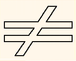 |
These three parts were aligned with the Align Point command.
The command expects a point to be selected which is to be aligned.
After issuing the command,
the user is asked to select a reference tangent.
The point will be moved into the (continuation of the) reference tangent.
Note that the reference tangent can be chosen from the
foreground or background character.
The Line up Points command causes a collection of points to be
on the same horizontal or vertical (imagined) line.
The points to be lined up are those selected when the command is
begun.
Typically, a scanning process will cause points,
which were horizontal on the original artwork, to be slightly off the
horizontal on the scanned image in the computer.
The Line up Points command will place all selected points
on a (invisible) horizontal line.
Formally, if the
vertical positions of the points
were closer to each other than their horizontal positions,
then the points will be put on an imagined horizontal line;
otherwise, the points will be put on an imagined vertical line.
The new position will be the mathematical average of the old values.
If the zoom factor is at most 1,
the new positions will be rounded to the nearest integer.
The Parallel command makes a curve slope (in particular a line)
parallel to another one.
Initially, that curve to be changed must have been selected.
The user is then asked by the command to select the curve end to remain
stationary.
(This selection is skipped if exactly one curve tangent has been selected).
Then the user is asked to select a tangent defining the reference slope.
The (end or control) point next to the stationary one on the selected curve
will be moved such that the resulting tangent is parallel to
the reference tangent.
Note that the reference tangent can be chosen from the
foreground or background character.
The Perpendicular command makes a curve slope (in particular a line)
perpendicular to another one.
Initially, that curve to be changed must have been selected.
The user is then asked by the command to select the curve end to remain
stationary.
(This selection is skipped if exactly one curve tangent has been selected).
Then the user is asked to select a tangent defining the reference slope.
The (end or control) point next to the stationary one on the selected curve
will be moved such that the resulting tangent is perpendicular to
the reference tangent.
Note that the reference tangent can be chosen from the
foreground or background character.
The Horizontal command makes tangents (in particular lines) horizontal.
Similarly as for the Adjust->Parallel command,
the curve to be changed must have been selected.
The user is then asked by the command to select the curve end to remain
stationary.
(This selection is skipped if exactly one curve tangent has been selected).
The (end or control) point next to the
stationary point will be moved into the horizontal of the stationary point.
The Vertical command makes tangents (in particular lines) vertical.
Similarly as for the Adjust->Perpendicular commands,
the curve to be changed must have been selected.
The user is then asked by the command to select the curve end to remain
stationary.
(This selection is skipped if exactly one curve tangent has been selected).
The (end or control) point next to the
stationary point will be moved into the vertical of the stationary point.
The Fit Spline command makes a path of Bézier curves optically pleasing.
The command acts as if it were taking a flexible
strip of material, such as a metal, and tying it to all the curve end points.
(In mathematical terms, the path curvature is made continuous by spline
fitting.)
That curve sequence must have been selected prior to entering the
Fit Spline commmand.
Several kinds of spline fitting are available:
- Relaxed
- Clamped
- Uniform relaxed
- Uniform clamped
Clamped splines are restrained to the slope
of the original path at both ends (as if held by clamps),
and do thus preserve smoothness with the neighboring curves.
Relaxed splines, also sometimes called natural splines,
become flat towards their ends (i.e., the curvature becomes zero).
If the curve path is closed, i.e., if it is a complete contour,
another kind of fitting is available.
Closed and Uniform closed
fitting act as if the plastic strip to be fitted is a loop,
i.e. the begin/end point of the path is treated like the other
end points points.
For nonuniform splines (chosen by Relaxed, Clamped, and Closed),
the lengths of the new curves depend on the distances of the original
curve end points, causing a smooth and rather tight fit of the new
curves.
Uniform splines (chosen by Uniform relaxed, Uniform clamped,
or Uniform closed choices)
will have all their curves of similar length.
This will cause short curves in the original path
to become much longer. Since curve
end points are not changed, originally short curves will thus
bulge out, causing a tighter fit for longer curves
and a looser fit for shorter curves.
The following figure shows a curve path with the start point at the lower
left. Sequence (1) is the original one before spline fitting.
The relaxed spline is shown in (2), the clamped spline is shown in (3),
and the closed spline is shown in (4).
The uniform relaxed spline is shown in (5), the
uniform clamped spline is shown in (6), and the
uniform closed spline is shown in (7).
A curve path and its fitted splines |
The spline type is selected from the spline type menu in the
input pop-up window.
Transformations include geometrical operations on characters,
such as rotating characters, producing mirror images (flipping),
enlarging or shrinking characters (scaling), and more.
Some transformations can be simultaneously applied to all characters in a
font.
Those transformations appear in the Edit Font
command group and are invoked with File->Font Edit.
To apply transformations also to the base point,
choose Yes from the Edit Base Point Menu in the
control panel.
Otherwise, make sure the menu is set to No.
All the following transformations operate on those parts of the character
that are selected prior to entering the command, with the exception
of Transform->Interpolate with.
The Transform->Project, Transform->Interpolate with, and
Transform->Align Axis commands apply only to curve characters.
All the other Transform commands apply to both raster and curve characters.
Shift shifts the whole character,
including its base point, with respect to the
character coordinate origin
(for raster characters, within the character matrix).
The user picks up an arbitrary hot spot with the
left mouse button, and drags it anywhere.
Alternatively, offset values may be entered directly into the
input pop-up window.
The OK button completes the Shift command.
A character can be shifted by repeatedly picking up any point in the
character window and dragging it. Arrows shift one unit into
the corresponding direction. SHIFT and CONTROL cause shifts of 10 and 50,
respectively.
For raster characters,
in order not to lose data, black pixels
or the base point may not be shifted out of the character matrix.
The difference between Shift and
Window->Scroll is that scrolling moves only the
visible rectangle to a different location within the character,
whereas shifting moves the pixels/curves in the character, thus modifying
the character.
This command is also applicable to guide lines;
see Guide Lines.
The focus serves as an origin for scaling.
It is thus the point which stays in its position throughout scaling.
Scale scales (magnifies or reduces) the selected features in the
current character by a factor in the range [0.01,5].
Increments are 0.01 or 0.0001 (choosing Fine).
The user is presented with a slider in the
input pop-up window, which shows the
range [0.01,5], from which the
scale factor is to be chosen.
The CONTROL-SHIFT-left mouse button resets the scale factor to 1.
Scaling modifies the character, as opposed to zooming, where only
the visible rectangle size is changed.
Two menus are presented in the input pop-up window:
In the menu Width one may choose whether to leave the character width
unchanged or whether to scale the character width by the scaling factor.
The menu Direction determines whether scaling is
uniform (in both horizontal and vertical directions),
horizontal or vertical.
Curve characters, being defined mathematically, are scaled precisely.
The raster scaling algorithm, however, produces only a
preliminary approximation result.
High quality raster scaling usually requires additional tuning by hand.
The focus is taken as the rotation center.
The Rotate command rotates the selected features in the
current character.
Rotation is possible by any angle in the range [0,360],
in 1 degree (or 0.005 after choosing Fine) increments.
The input pop-up window shows a slider on which the angle can be chosen.
The CONTROL-SHIFT-Left mouse button resets the angle to zero.
The Skew command skews (slants) the whole current character,
either in the horizontal or vertical direction.
The focus acts as the skewing center
(i.e., it marks the row or column that will stay in place).
Characters can be skewed by any angle in the range [-45,45] degrees,
in 0.5 degree increments (or 0.0025 after choosing Fine).
Subsequently, the angle is chosen on the displayed slider.
The R11 key resets the angle to zero.
Skewing is changed from horizontal to vertical and back with the
Direction menu in the input pop-up window.
This command is also applicable to guide lines;
see Guide Lines.
Mirror Window mirror-images
the selected features in the current character around the focus,
either horizontally, vertically, or in both directions.
Horizontal and vertical mirroring are achieved by setting the
appropriate menus in the pop-up input window.
Project performs a perspective transformation on
the contents of the only selected window.
Each of the four corners can then be moved by
depressing the left mouse button over the corner and dragging it.
Releasing the left mouse button determines the new corner location.
The projection is determined such that the quadrangle will
be the image of the originally selected rectangular window.
In the input pop-up window, the coordinates of the previously modified
window corner point can be changed directly.
Clicking the OK button completes the command.
Note that, for curve characters, only the curve points within the
rectangular window are projected, possibly yielding unintended results
for curves with points inside as well as outside the window.
Since nonconvex quadrangles will always contain vanishing points,
TYPO enforces that only convex quadrangles can be formed
(a quadrangle is convex if all its angles are less than 180 degrees).
Interpolate with performs an interpolation between the
current character and another character from the current font.
A new character is generated that is a blend of those two characters.
The user is prompted for an interpolation character
(see Character->Open Character).
The current character will be interpolated with this other character.
Then correspondence points can be determined (more about this later).
After pressing the Interpolate button,
the user is presented with a slider on which to choose
the interpolation ratio (initially 0%). This ratio determines
how much each of the two characters contributes to the resulting character.
A value of 0% indicates that the resulting character will be identical
to the former current character, and a value of 100% indicates that the
resulting character will be identical to the interpolation character
taken from the current font.
A value of 25%, for instance, prescribes that the
new character is blended 75% from the current character and 25% from
the other character. (This blend is mathematically obtained by
connecting each point on the current character to a point on the
other character with a straight line. Then the point on that line is chosen
which divides the line in the ratio 25% by 75%.)
While determining the interpolation ratio,
each time the left mouse button is released or an arrow is hit,
the temporary result is shown.
Clicking the OK button finalizes the result and completes the command.
Clicking the Mark Points button lets the user change the correspondence
points, and the interpolation operation can be aborted by clicking
the Cancel button at any time.
Each character consists of one or more paths (separated by movements).
If the number of paths is unequal, the character with less paths
is given additional ones by subsequently splitting each path, from
the first one to the last one.
For example, if the current character has only two
paths (like in the letter A),
and the other character has three paths (like the letter B),
then the first path in A gets split in its middle into
two paths.
Similarly, if a path from the current character consists of
a different number
of curves than the corresponding path in the other character, then the
path with less curves is adapted by successively splitting curves
in two, from left to right, until the number of curves are equal.
The user can control this path and curve splitting process by specifying
correspondence points, both in the current and in the other character.
A correspondence point is set by being selected, and is shown
highlighted, with the running number of the path that it begins.
A correspondence point is unset by being selected again.
To set correspondence points in the other character, press the
Swap Characters button. The same button also switches back to
the current character.
A correspondence point specifies an end-of-path.
The user can thus prescribe
which features of the current character get blended with
which features in the other character. The user selects
correspondence points in both characters such that the number of
paths becomes equal.
Moreover, features to be blended
with each other must bear the same correspondence point numbers
at their respective path begin and end points.
During the interpolation process, new correspondence points can be
defined by pressing the Mark Points button.
The Align Axis command is a variation on Transform->Rotate.
When scanning artwork, it is nearly impossible to scan in the
original such that lines horizontal or vertical in the original
remain so after scanning. Typically the scanned image appears
rotated at some small angle.
After outline tracing, there is the need to align the character along
some reference line (for instance, the left boundary of the vertical
stem in the character 'E' in most roman fonts).
This is done with the Align Axis command.
Two curve points must have been selected upon entry to the
Align Axis command
(for instance the upper and lower end of the vertical line in the letter
'E').
The character gets rotated around the center of the line that connects these
two points such that the two points become aligned horizontally
or vertically, whichever can be achieved by rotating around the
smaller angle.
The Metrics group of commands defines the base point, the width,
and the kerning for both raster and curve characters.
Symbols on one print line are laid out such that all their base points
are on one horizontal line, called the base line.
The horizontal distance from the base point of a symbol to the next base
point is given by the width of this symbol.
This is illustrated in the following figure.
Character metrics |
The base point of the next symbol is thus usually positioned
at the current base point plus the current width.
The left bearing is the distance between the
base point of the character and the beginning of its black area.
Similarly, the right bearing is the distance between the end of its
black area and the base point of the next character
(i.e., its own base point+width).
In extremely bad cases, kerning is performed to improve some
particularly bad character pairs. Examples for this are shown in the
section on Kerning.
Base point locations, widths, and
kernings are defined or changed with the
Metrics group of commands. These commands are equally applicable to
curve and raster characters.
Set Base defines a new base point for the current character.
The user positions the base point to determine the new
location. The old base point is displayed shaded for the time of
the command.
The BX and BY
fields in the Character Properties Window
are permanently updated during the positioning process.
It is recommended to use the Typeset facility while setting the base
point; base point inconsistencies with other characters can immediately
be recognized and corrected.
The Set Base command is analogous
to selecting the base line
and performing the Transform->Shift command.
In some cases, the base point is required to be at the exact center of the
character.
This is done with Center Base.
An example of the usefulness is for pens.
There, the base point defines the point at which the mouse drags the pen,
or the point at which the pen is to move along curves for
painting.
For certain shapes, such ar circles, the pen is preferably
dragged at its center.
Set Width defines a new width for the current character.
The base point is not moved.
A dashed line is displayed which indicates the old character width.
The user positions the new width, visible as a
solid line.
This command effectively modifies the right bearing without changing
the left bearing.
The W field in the Character Properties Window
is permanently updated during the positioning process.
It is recommended to use the Typeset facility
while establishing the character width.
The Set Width command is analogous
to selecting the Wi guide line
and performing the Transform->Shift command.
Set Width Left defines a new left bearing for the current character.
This command modifies thus the character width,
moving only the base point
and not changing the right bearing; i.e., distances to following characters
are preserved.
Except for the different side of the bearing,
this command acts like Metrics->Set Width.
The Set Width Left command is analogous
to selecting the Ba guide line
and performing the Transform->Shift command.
The Copy Bearings from command copies the left and the right bearings
of another character to the current character.
The user is asked to input the character position or name of
the character to copy the bearings from.
For instance, characters which are identical except for accents will
usually have the same bearings.
Therefore, the bearings of the accented character can be copied from the
unaccented character.
Effectively, the base point horizontal value and the width
are set.
The Copy Left Bearing from command copies the left bearing
of another character to the current character.
The user is asked to input the character position or name of
the character to copy the bearing from.
Effectively, the base point horizontal value and the width
are set.
The Copy Right Bearing from command copies the right bearing
of another character to the current character.
The user is asked to input the character position or name of
the character to copy the bearing from.
Effectively, the width is set.
Kern with adjusts the width for specific character pairs, where
using the standard width would produce optically bad spacing.
This command is described in detail in the section on Kerning.
Copy Kern from
copies the kerning information from one character to the current character.
This command is described in detail in the section on Kerning.
Kern Same as makes the current character kern like
some other character.
Unlike Metrics->Copy Kern from, this command causes both characters to
share the same kerning table; changing that kerning at some later time
will affect both characters.
This command is described in detail in the section on Kerning.
Unkern deletes all kerning information from the current character.
This command is described in detail in the section on Kerning.
This submenu contains the commands handling hints.
These are described in the section on Hint Commands.
Embolden artificially emboldens a character by replicating each
black pixel that precedes a white one, in the emboldening direction.
Emboldening is caused by pressing the Embolden button, thinning
is caused by pressing the Thin button.
Emboldening is either horizontal, vertical, or uniform
(i.e., both horizontally and vertically), depending on the Direction menu.
A single curve must be selected prior to entering the command.
The Curve Properties command shows the properties of the selected curve;
its kind, whether it is rigid or flexible
(see Hint Commands), and its coordinates.
All these properties can be modified as well.
To see the effect of the changes, press the Apply button.
To make them final, press the OK button.
This command is also applicable to guide lines;
see Guide Lines.
Example curve property and guide line property pop-up windows follow.
Curve Property Window |
Guide Line Property Window |
The direction of a contour in the current character
can be reversed with the Reverse Path command.
If the contour is closed, it can be revolved,
such that a different point on that contour becomes the close-up point.
This command is particularly useful in connection with
the even-odd and wrap count filling strategies as described in
the section on Painting Curve Characters;
there, to achieve the desired filling effect, it is often necessary
to reverse the direction of a contour.
The contour must be selected prior to entering the command.
Pressing the Rotate Forward button advance the close-up point,
and pressing the Rotate Backward button will move the close-up point
to the previous point on the contour.
The contour is reversed by pressing the Reverse button.
Note that, after the contour is reversed/revolved,
incoming and outgoing movements
are updated to the new begin/end points of the path.
Any close-ups on the contour itself will be reversed if the path is reversed.
Reversing a contour requires that path to be connected to the rest of
the character only with movements.
It is also possible to operate with this command on a path containing
several contours;
one may, for instance, reverse a whole character.
The Split Curve command splits a curve into two or more curves of
the same kind
(i.e. a line gets split into lines, a Bézier curve into Bézier curves, etc.).
The new curves, taken together, will exactly cover the original curve.
The user selects the curve to be split before entering the command.
The user can then position an arbitrary point on the curve at which
to split it into two.
Alternatively, the user can split the curve by choosing an entry from the
Split at menu.
Possible choices depend on the type of the selected curve.
All curve kinds can be split at their midpoints.
In addition, Bézier curves and arcs can be split at their
minima and maxima by choosing Extrema,
and Bézier curves can also be split at their inflection points by choosing
Inflections.
Join Path
joins a path consisting only of Bézier curves into a single Bézier curve.
The resulting curve will approximate the original path as closely as possible.
The primary purpose of this command is to reduce the number of Bézier curves used,
thus making the character optically more pleasing.
Prior to entering the command, the user must have selected
the path to be joined.
TYPO will not join curves is there is any hint
inside the path.
Curve Kind changes a curve from one kind
(Bézier, arc, line, or movement) into another.
The only conversions that are illegal are from lines and movements to arcs.
The user selects a curve to be converted.
The new curve kind can be chosen from the
Curve Kind menu or be stepped with the arrows.
On converting arcs to Bézier curves,
each arc is approximated by up to four Bézier curves, each one for
an angle of up to 90 degrees.
Each such Bézier curve is determined by its end point coordinates,
the slope at its end points, and mid-point coordinates.
On converting Bézier curves to arcs,
each Bézier curve is approximated by a sequence of arcs, as follows.
First, the curve is subdivided at its horizontal and vertical
minimum and maximum points and at the inflection points (an inflection
point is a point where the sense of rotation changes from clockwise
to counter-clockwise or vice versa, just like in the middle of the
letter S).
Each such subcurve is approximated by six arcs.
Note that changes to the curve kind in the Curve Kind command
differs from changes in Special->Curve Properties.
In the former command, a Bézier curve is, for instance,
converted to arcs by approximation with a number of arcs.
In the latter case, a Bézier curve is converted to a single arc such that
both end points and the slope at the
beginning are preserved. No approximations take place.
Outlines of characters typically consist of closed-up contours.
One way of closing up a contour is at the time of its creation, as described
for the Bézier Curve Drawing Tool.
Closing up can also be done explicitly with the Close up command.
The user selects a curve at the end of a contour; this curve
will be closed up to the opposite contour end.
A closed-up curve is drawn in
the character window with an arrowhead at its end.
Note that a curve may not be closed up to itself.
Frequently certain shapes occur in more than one character within
a font.
A typical example are serifs.
In some fonts, the serif of the letter 'i', for instance, has the same shape
as the serifs on the letter 'n'.
With TYPO, every character can be constructed
using the elementary curves
(Bézier curves, lines, arcs, and movements), or more complicated
user-defined building blocks (which are built out of the same
elementary curves).
Another typical case are letters with diacritical marks.
The letter a will be the same whether it appears as an umlaut
or with an accent.
In both cases above, we want to construct the repeating element only once,
and keep it only once such that every modification to it will be propagated
throughout the whole font.
This is achieved by using the sub-character feature of TYPO.
These repeating elements are called sub-characters. Their only
difference from ordinary (main) characters is that they may
not contain sub-characters themselves;
sub-characters must be defined with the elementary curves only.
Sub-characters are stored in the font like other characters.
For example,
a serif can be created once, stored in the font as a sub-character,
and then be called from other characters.
Modifying this serif will cause consistent changes in all the characters
which call the serif.
For example, the letter 'n' and the letter 'i' in the following figure
both call the same serif; in fact, 'n' calls the same serif twice.
The spurs at the upper left of both characters are sub-character calls
as well. These sub-character calls are shown dashed.
Common sub-characters in i and n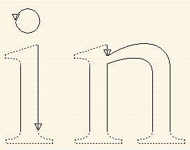 |
Accented characters are constructed from a base character and an accent.
The base character itself is, however, a main character
(such as the letter A).
For this purpose, TYPO has callable main characters.
A callable main character is defined like a sub-character
(it may thus not contain other sub-character calls).
It is, however, a legal main character by itself.
One can see from the
Character Properties Window
whether the current character is a
main character, a sub-character, or a callable main character;
Char is replaced by SubC or by CallC, accordingly.
For background characters, Over is replaced by
SubO or by CallO.
A sub-character is initially created like any other character.
Then it is changed into a sub-character with the
Callability command. The same command can also be used to
convert a sub-character back into an ordinary (main) character.
The user is presented a menu in the input pop-up window.
There, one of three possible choices can be made:
- Main Character
- Callable Main Character
- Sub-Character
Note that a main character cannot become a sub-character
if it calls other sub-characters;
i.e., nested sub-character calls are illegal.
Vice versa, a sub-character in a font may not be replaced by a
non-callable main character if that sub-character is being called
from other characters.
A sub-character (from the font of the current character)
is called into the current character with the
Call Sub-Character command.
The curve after which to insert the sub-character must have been
selected upon command begin.
The user is then prompted for the character to be called
(as in Character->Open Character).
The sub-character is shown dashed.
The command Replace Call with
replaces the call for one sub-character to a different one.
The sub-character to be replaced must have been selected prior to the command.
The user is then asked to input the character code
of the new sub-character to be called
(as in Character->Open Character).
The Expand Call command causes a sub-character call in the
current character to be expanded, i.e. the call is deleted,
and a copy of the called character path is inserted instead.
The call to be expanded must be selected prior to this command.
This command is typically used if a character is to be scaled, skewed,
or alike (see Transform Commands),
or if a character feature is to be changed
independently of the other characters in the font
(for example, if it is desired to change the serif of the letter 'i'
without changing the serif of any of the other letters).
Each called sub-character code (in decimal) is shown above the
respective sub-character. The command is terminated
(and the codes disappear) if any key or button is hit.
Hints overcome several of the problems that arise when converting
outline characters into raster images for printing.
Take for example the letter 'n'.
Even though the two stems of the letter n
are of equal width in the outline character, rounding them to the
grid causes the stems of the printed character to be unequal.
An example is shown in the following figure.
Unequal stem widths due to rounding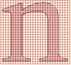 |
Hints inhibit this situation by aligning each hinted stem
and each hinted beam (beams are also often called crossbars)
on the raster grid before converting the
character into the final raster. This is depicted in the following figure.
Equal stem width after hinting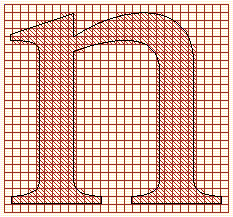 |
A frequent problem in character rasterization is illustrated in the
following figure.
Too short and too long runs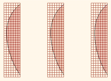 |
A Bézier curve can, due to grid alignment, yield either too short
(middle figure)
or too long (right figure) pixel sequences at curve minima or maxima.
This problem is overcome by hinting each curve minimum or maximum,
such that the curve is pulled to the pixel boundary (left figure).
TYPO applies these implicit hints unless inhibited by the
Hints option (see File->Options).
The Hint Stem command will cause two points
(often one beside the other) to define a character stem.
Note that character stems can be real stems
(as described above for the letter n), or small stems,
for instance the vertical serif at the right end of the middle bar
in the capital letter 'E'.
The two points describing a stem,
together with all other points occupying the same x coordinates,
will become (horizontally) aligned on the raster grid, on final conversion
(printing on the printer, Typesetting,
Edit->Raster<->Curve, or Edit->Insert Text).
The user is prompted to select
two points, which will define the left and right end of the stem.
Each of the two points will be marked with the same alphanumeric symbols,
inversed white on black.
Different hint pairs will be marked with different symbols.
Thus, to assign hints to the stems of the letter 'n'
(see the previous figure, the user should select
one point on the left side and one on the right side of each stem,
and one point on the left side and one on the right side of each
serif at the bottom of the stem.
All curve end points between hints are (horizontally)
moved such that they preserve
their horizontal relation with the hinted points.
This is illustrated in the next figure.
Preserving left-right for hints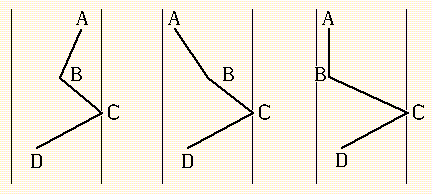 |
Assume that point A is hinted, and that (1) is the situation
before raster grid aligning. If aligning A were to yield situation (2),
then B is moved to the left (see (3)),
such that the x coordinate
of B will again be less or equal to that of A.
Hint Beam places beam or crossbar hints.
It works like Hint Stem, only in the vertical direction.
Hint Both places a stem as well as a beam hint between two points.
An example is the creation of a circle, to be
perfect at all resolutions.
It is recommended to go through
the following steps:
- Use the Center Ellipse Tool
- Place mouse at the center point
- Depress the left mouse button
- Drag the mouse to create the circle
- Release the left mouse button
- Make radii equal and press Apply
- Click OK
- select the top and the bottom curve end points
- Issue Hint->Hint Both
This will cause the circle to be symmetrical at any resolution.
The Adjoin Stem command will cause a point to be aligned together
with a stem hint pair (see Hint->Hint Stem),
as if it were connected to one of these points via a rigid
connection (see Hint->Rigid/Flexible).
Points that are no adjacent on the curve path may thus be synchronized
with each other; if the hinted point pair gets moved for adjustment,
an adjoint point will get moved together with them.
The user is prompted to select
two points: the first point must already bear the hint
with which the second point is to be adjoined.
An adjoint point is marked with the hint symbol, black on white
background (as opposed to regular hints, which are marked white
on black).
The Adjoin Beam command will cause a point to be aligned together
with a beam hint pair (see Hint->Hint Beam),
as if it were connected to one of these points via a rigid
connection (see Hint->Rigid/Flexible).
Points that are no adjacent on the curve path may thus be synchronized
with each other; if the hinted point pair gets moved for adjustment,
an adjoint point will get moved together with them.
The user is prompted to select two points:
the first point must already bear the hint
with which the second point is to be adjoined.
An adjoint point is marked with the hint symbol, black on white
background (as opposed to regular hints, which are marked white
on black).
In high quality type, letters with round shapes may extend
below the base line; this is called
base line overhang.
Take for instance the letter combination 'Lo' as illustrated
in the following figure.
Base line overhang of the letter o |
For rather small point sizes, if the letter were still to extend below the
base line, this would yield unaesthetic results;
a one-pixel overhang is, for instance, too large for a 10-pixel character.
In TYPO, this point size dependency is described as follows.
The type designer can determine a threshold point size
below which overhangs should not occur.
This threshold size is specified (separately
for the horizontal and vertical direction, relative to the device resolution)
with the font properties
Horizontal Threshold, Vertical Threshold, and at Resolution
(see File->Font Edit->Properties).
For example, if overhang suppression is to occur below a point size of
10 points for a 300 dots/inch printer, these properties are
set to the values 10, 10, and 300.
The threshold is relative to the resolution. For printers with
600 dots/inch, the values 10, 10, and 300 will cause overhang suppression
below a point size of five points (i.e. this is the same as setting the
options to 5, 5, 600).
There are two different ways of specifying thresholds in TYPO.
The first one, only applicable in the vertical direction,
ties a hint pair to a guide line.
If the point size is above the threshold value, the hint in the overhang
keeps its position; otherwise, it will be moved to the
guide line.
This is illustrated in the following figure.
Placement of hints for overhangs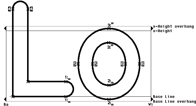 |
Note first that the the letter 'O' is hinted at its bottom
(marked by 2).
The symbol 2 is followed by a pair of lines.
This symbol describes a two-point hint whose lower point lies within the
overhang alignment zone of a guide line. In this case, it is the base line.
If the point size is less than the threshold point size,
then the the hinted points
(together with their neighboring control points)
are moved such that the lower point coincides with the base line.
Otherwise, these points take their original coordinates, and act as a
regular beam hint pair.
Note also that the (lower) beam of the letter 'L' is
hinted (marked by 1).
This hint enforces that the beam of the letter 'L' will always
be placed exactly at the base line. If this was a normal beam hint,
the beam could, because of beam centering as described above,
be possibly placed one pixel too high or too low.
The other hint placements were determined as follows:
Tie hint 3 controls the overhang of the letter 'o' with respect
to the x height.
Stem hints 5 and 6
cause the left and right side of the letter 'o' to always be of equal width.
Stem hint 4, together with the beam tie hint 1,
cause the stem and beam of the letter 'L' to be of identical width.
The following figure shows the same character pair of the previous figure,
with the threshold increased
such that the point size falls below the threshold.
The letter o without overhangs |
Only beam hints can be tied to guide lines.
There is another way of tying hints in TYPO which is possible both
for stem and beam hints.
Rather than tying hints to guide lines, these can be tied to other points
in the character.
The dot in the letter 'i', for instance, will usually
be somewhat wider than the letter stem itself.
At small point sizes, they
should have the same width. Moreover, the dot should be centered
above the stem at small sizes.
Such hints are shown in the next figure.
To achieve all these properties, stem hint
2 on the dot is tied to stem hint pair
1 on the stem. This is denoted as 2 <-> 1.
If the point size is smaller than the threshold point size,
the points in hint pair 2 will be moved
to the horizontal positions of hint pair 1.
The definition of the letter i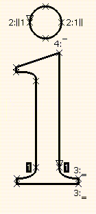 |
We also note that the stem top of the letter 'i' bears a single
hinted point 4. This point lies in the x height
overhang alignment zone, and is tied to the x height guide line.
Whenever the point size is below the threshold point size,
that point will be vertically moved to lie exactly at the x height.
The capital letter 'I', for example, would have to be given two such hints,
one for the base line and one for the cap height.
The Tie Stem command defines a stem tie hint or a
stem tie hint pair.
Prior to entering the command, the user must have selected one or two
stem-unhinted curve points and one stem-hinted curve point.
In the figure above, the user selects the left and right points of
the dot in the letter 'i'. The user also selects one of the
points marked with 1.
Then the two points in the dot get tied to the stem hint marked 1.
If there are two unhinted curve points,
the user defines these as a new tie hint pair.
If there is only one unhinted point, the user defines it to be tied
to the selected hinted point.
A vertical bar to the left of the hint designator indicates that
this point is tied to the left point in the original hint pair.
A vertical bar to the right of the hint designator indicates that
this point is tied to the right point in the original hint pair.
The Tie Beam command is analogous to Hint->Tie Stem.
It defines a beam tie hint or a
beam tie hint pair.
Prior to entering the command, the user must have selected one or two
beam-unhinted curve points and one beam-hinted curve point.
If there are two unhinted curve points,
the user defines these as a new tie hint pair
which is ties to the beam hint pair of the selected (hinted) point.
If there is only one unhinted point, the user defines it to be tied
to the selected hinted point.
A horizontal bar above the hint designator indicates that
this point is tied to the top point in the original hint pair.
A horizontal bar below the original hint designator indicates that
this point is tied to the bottom point in the original hint pair.
As shown in the last figure for hints 3 and 4, it is also possible
to tie pairs or single points to guide lines
rather than to other hint pairs.
A beam point is tied to a guide line with the command Tie to Guide.
Prior to the command, the user must have selected a single curve point
in the overhang alignment zone of a guide line,
or a point pair where exactly one of the points is in the
overhang alignment zone of a guide line.
A horizontal bar above the hint designator indicates that
this point is tied to a guide line whose overhang alignment zone is above.
A horizontal bar below the original hint designator indicates that
this point is tied to a guide line whose overhang alignment zone is above.
Two lines are shown if this is a hint pair which is tied.
The Unhint Stem command deletes a stem hint, adjoint or tie.
The user selects a hinted, adjoined or tied point.
If this is a hint, all the points belonging to that hint will become unhinted,
as become all the adjoining and tied points referring to that hint.
If the selected point is an adjoining or tied point,
the adjoint or tie gets deleted.
The Unhint Beam command deletes a beam hint, adjoint or tie.
The user selects a hinted, adjoined or tied point.
If this is a hint, all the points belonging to that hint will become unhinted,
as become all the adjoining and tied points referring to that hint.
If the selected point is an adjoining or tied point,
the adjoint or tie gets deleted.
The Rigid/Flexible command makes a curve rigid if it was
flexible, and makes it flexible if it was rigid.
Since hinting
(see Hint->Hint Stem, Hint->Hint Beam, and Hint->Hint Both)
involves moving points,
some curves become either stretched or shrunk during the rasterization process.
A rigid curve is not stretched/shrunk.
The user selects the curve to be made rigid or flexible.
A rigid curve is marked with two small squares, one at its beginning
and one at its end.
On PostScript output devices with small memory,
TYPE 3 fonts generated with hints are sometimes too big for that memory.
A VM Error message is obtained in this case.
This problem can usually be overcome by either outputting
PostScript TYPE 1 fonts, or by ignoring the
hints while outputting PostScript TYPE 3 fonts.
Unfortunately the usefulness of hints is lost in the latter case.