TYPO is a tool kit for (typo)graphic artists and technical writers
to create and maintain sets of characters, logos, or icons
(icons are images typically displayed on a screen and
representing some computer program or file).
These symbol sets, called fonts,
can then be shown on laser printers, photo typesetters, or graphic displays.
TYPO supports two kinds of symbols: raster symbols or curve symbols.
These two kinds are totally different in nature.
A raster symbol may be thought of as a collection of squares in a grid
(or points in a rectangular matrix);
each square is either black or white, as illustrated here:
A raster character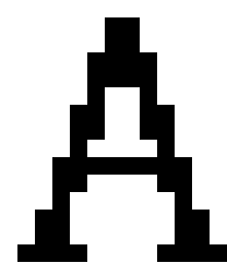 |
The symbol size is usually fixed by the device it is used on;
each square in the symbol
determines the color of a basic dot (called pixel) on the device.
Curve characters, on the other hand, are described mathematically.
The outline of the character is described by a sequence of
straight lines, circular arcs, or Bézier curves
(named after the scientist who introduced these
curves into computer-aided design, Pierre Bézier).
For some characters, such as the letter o,
the curve sequence consists of two contours;
one describes the exterior boundary of the character, and the other
describes the interior one.
In each of these two parts, the last curve is closed up to the first curve.
The two parts are connected by an invisible line, called a movement.
The curve description of the letter o is shown here:
A curve character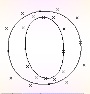 |
Bézier curves run from their start point to their end point.
In addition, they have two auxiliary control points.
These control points determine the slope of the curve at the curve start and
end points, as well as the curvature.
For a Bézier curve, see this figure:
A Bézier curve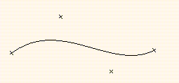 |
We can see that the slope of the curve at the start point
is the same as the slope of the straight line connecting the start point
to the first control point.
This is also true for the end point, using the second control point.
We call those (imaginary) lines which connect the end points to their
respective neighboring control points tangents, as they
touch the curve at their end points.
The control points also determine the curvature, by pulling
the curve towards them.
For instance, stretching the first control point above further up,
we obtain the curve in the following figure.
As can be seen, the left part of the
curve is pulled further upward.
The modified Bézier curve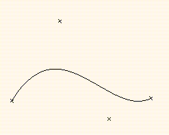 |
Bézier curves have thus the advantage of easy and intuitive handling by moving
one of their end or control points; rotating a control point around its end
point changes the angle of the curve at that end point,
pulling a control point away from its end point
will "stretch"; the curve towards that direction.
We have described tangents for a Bézier curve to be the (imaginary) lines
connecting the curve end points with their respective neighboring
control points.
Their slopes are thus identical to those of the curve at the corresponding
end points.
Tangents of circular arcs are defined in the same way.
Analogously, the tangent of a line or movement is that line or movement itself.
Curve characters, being described mathematically
by their Bézier curves, lines, arcs, and movements, have many advantages
over raster characters. They can be blown up or reduced (scaled)
to any size, they can be rotated by any angle, they can easily be slanted,
they can be stored compactly (only the curve points and some additional
minor information have to be stored), and many more.
The two symbol kinds described above are completely different in nature.
TYPO handles both kinds, and can automatically convert curve into
raster symbols and raster symbols into curve symbols.
Raster to outline conversion involves approximating a discrete pixel image
by mathematical curves. This process can, by its nature, not be
absolutely precise and will frequently require manual corrections.
TYPO supports these corrections in several ways.
On one hand, it allows placing the raster character behind
the curve character on the same screen, so that
the user can easily make the desired corrections based on the original shape.
On the other hand, TYPO has a variety of Adjust commands
that precisely position curves and lines with respect to other curves or lines.
For example, lines can be made parallel to others,
and corners can be smoothed.
The frame layout is shown in the following figure,
and the meanings of the individual windows are shown in thereafter.
A TYPO frame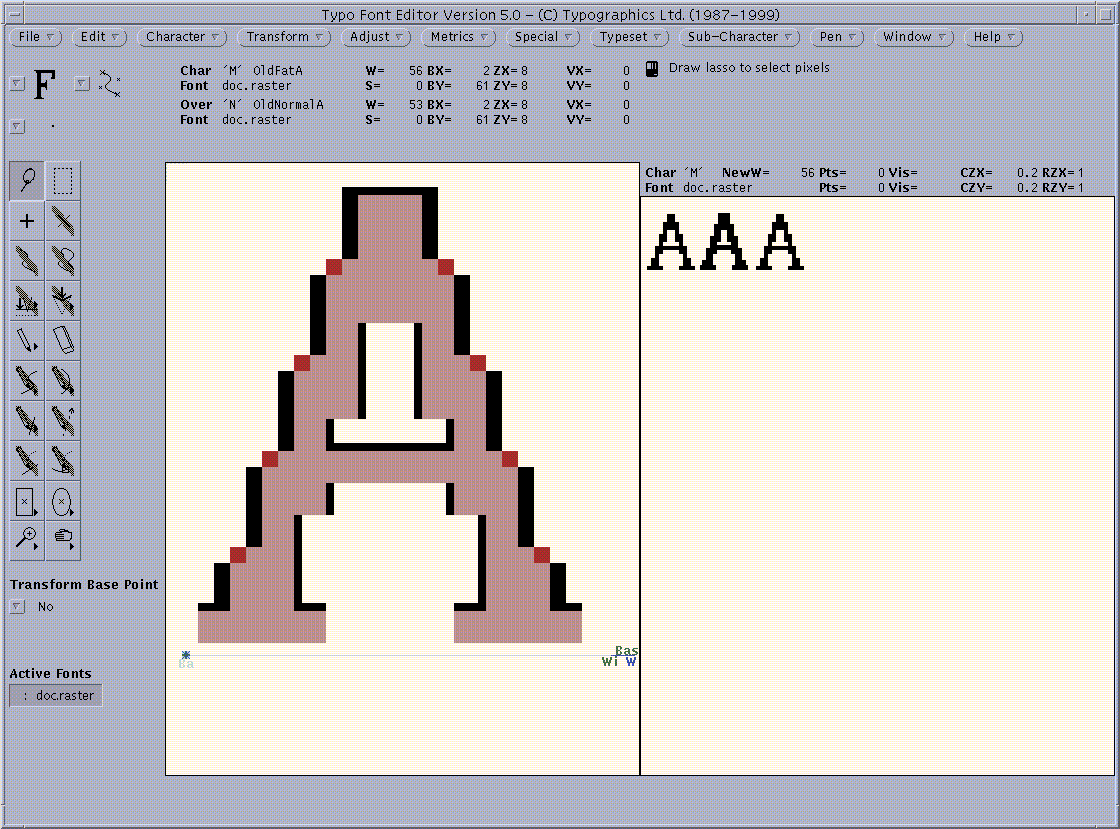 |
The TYPO window is begun, from top, with a bar that contains all the
command menus of TYPO.
The commands are grouped by their function;
File,
Edit,
Character,
Transform,
Adjust,
Metrics,
Special,
Typeset,
Sub-Character,
Pen,
Window.
They will be described later in detail.
An example is the command File->Exit,
i.e., the Exit command in the File command menu.
Some commands are grouped in submenus inside a menu,
such as the command File->Font Edit->Properties
inside the File->Font Edit menu, which is, in turn, inside the
File command menu.
A command is executed by choosing it from its menu;
pressing the right mouse button over the menu header,
choosing the appropriate command with the mouse,
and releasing the right mouse button.
The control panel contains, from top to bottom, left to right:
- The Foreground/Background Menu
- The Curve Detail Menu
- The Pens Menu
- The Toolbox, a menu of tools for selection,
modification, or viewing of characters
- The Edit Base Point Menu, specifying whether
transformation commands also apply to the base point
- The Active Fonts Menu,
containing up to four font names
(In our example figure, the font doc.raster). The current choice
indicates the current font,
i.e., the font to be used for the current operation,
such as File->Font Edit->Layout Font, or
Character->Open Character.
The character window may contain up to two characters, one in the
foreground and one in the background.
With a few exceptions, the commands and tools of TYPO will typically
operate on one of these characters.
By default, that character will be the foreground character.
This may, however, be changed with the
Foreground/Background menu.
There, the user can specify whether the foreground or the
background character is to be operated on.
For simplicity, we refer to that character that will be operated on
as the current character.
More on background characters appears in the
Background Characters section.
This is shown in the figure below. Black squares belong only to the
current character,
brown squares belong only to the background character,
and pink squares belong to both.
These colors can be changed with the Window->Colors command.
In fact, the user may perform certain operations on the current character
guide lines instead of the character itself.
This can also be specified in the
Foreground/Background Menu,
and is described in the section on guide lines.
A raster character with a background character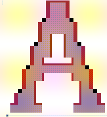 |
The character properties and background character properties
windows show various important data about these characters,
and are described in the section on Character Commands.
The Typeset Window is used to display the current character
in the context of any text, even taken from another font.
The main purpose of this screen is to judge the overall appearance
of the character, to adjust its placement, its width, etc.
The Typeset properties window will display a list of relevant values
for the typeset screen.
An example of such a list is shown below:
An example typeset properties window
Char 'A' NewW=35 Pts=10 Vis=15 CZX=0.001 RZX=2
|
Font OurRomanFont Pts=15 Vis=18 CZY=0.001 RZY=2
|
This example typeset properties window contains the following items:
- The current character is 'A' (65).
- The current curve zoom factor, for curve characters in the
typeset window,
is 0.001 in both directions CZX and CZY).
- The current horizontal and vertical raster zoom factors,
for raster pixels, are (2,2), as displayed in (RZX,RZY).
- The current character width,
scaled according to the present typeset window
curve zoom factor, is 10 (NewW).
- The point size (Pts) of the current character,
at the present curve zoom factor, is 15. For this size value,
one pixel on the printing device will correspond to one pixel on the screen.
Even though the character on the screen will typically be much larger
than the character of the same point size on paper, both characters
will occupy the same number of pixels, and, hence, the character
shown on the screen will give a good idea what the final character on paper
will look like.
- The visual size (Vis) is 15.
The visual size is the physical size of the character on the screen,
measured in points.
The screen character will typically consist of less pixels than that on paper,
since screen resolution is typically lower than the printer resolution.
- The font OurRomanFont
is used for typesetting
(i.e., all the characters in the typeset text
other than the current character are shown in this font).
Its point size is 15, and its visual size is 18.
For curve fonts,
this point size is obtained by multiplying the font point size
with the curve zoom factor, and then adjusting for the printing
device resolution.
The visual size is computed by adjusting for the display device resolution,
i.e., multiplying the resulting point size with the ratio
(device resolution)/(screen resolution).
Screen and device resolutions are specified in the
Options window.
For raster fonts, only the point size is displayed.
It is always identical to the font point size.
The reason for this is that, for raster fonts, screen pixels
always correspond to printed pixels.
The mouse button and arrow description window displays,
for each function and context,
the presently applicable mouse buttons, together with the functions that they
will perform.
It is also shown which of the
eight arrows (keys R7 through R15)
are applicable at any time, and what function they will perform.
The messages and errors window guides
the user through the operations with explanatory messages, and it
displays the error messages.
The input pop-up and tracking information window sets values and
options for commands and displays relevant command information.
For many commands, it will display coordinate values
and other tracking information.
For commands requiring the setting of options, menus with the appropriate
choices will be displayed.
For commands requiring textual or numeric input, such input may
be typed using the keyboard.
After changing any of those options or values,
the user must typically press the Apply button
to make these settings effective.
Some commands are governed by a single value to be set,
such as a rotation angle or a scale factor.
There, the window contains a slider on which the user determines
the input value.
Setting the value on the slider will automatically make the changes effective
and there is no Apply button in the presence of a slider.
The particular use of this window is described separately for the various
commands.
This window contains two additional buttons;
OK will finalize the command, keeping the changes,
Cancel will abort the command,
discarding the changes introduced by this command.


