 |
 |
Next, issue the command Character->New Curve Character. The Character Properties Window will display Char NEW, together with some additional information, to indicate that this is a new character that was just created.
Choose the Bézier Curve Drawing Tool from the toolbox, by clicking the left mouse button over that tool. This tool expects (on an empty character) that you position the start point. This will be the point at which the first curve of the symbol outline begins. Depressing the left mouse button will fix a tentative position, and a marker is displayed on the screen showing your choice. If you do not like that position, just move the mouse elsewhere, still keeping the mouse depressed. To finalize your choice, release te left mouse button. This will fix the start point, and you are now ready to append your first curve of the symbol outline.
This process of depressing the left mouse button, choosing a position with the left button depressed, and releasing the left mouse button upon reaching the desired position, is called dragging.
To add a Bézier curve, proceed just as for the start point, dragging the first control point, the second control point, and the curve end point. After the end point has been placed, the three auxiliary lines connecting these points are automatically erased and replaced by the Bézier curve.
To append a straight line, choose the Line Drawing Tool from the toolbox, by clicking the left mouse button over that tool. Then, place the line end point. The line is now complete.
Arcs are painted similarly to Bézier curves. An arc, however, is mathematically determined by the start point and two control points (as opposed to Bézier curves which also require the end point specification). The arc is thus automatically completed after the user has determined the second control point.
A movement is an invisible line connecting between character contours, such as the outer and the inner loops of the character o. It is appended similarly to a line. Since it is invisible, only its start and end points are displayed, with no curve or line connecting them.
A contour is closed by placing the last point of a curve over the start point. The curve, arc, or line will then end at the initial contour start point, and an arrowhead will be added to mark that the curve closes up.
If you want to draw another contour, you will first be required to draw a movement to the start point of the next contour (the change to the Movement Drawing Tool and back happens automatically), and then to draw the contour itself.
Having completed the character, an asterisk will appear to the left of NEW in the Character Properties Window. This asterisk indicates that the character was modified but not yet saved.
Assume now that you do not like the position of one of the points. To change the location of that point, choose the
If a new Bézier curve, a line or an arc is to be connected smoothly to the previously placed curve, such that no corner is to be present at the connecting point, the Smooth Bézier Drawing Tool, Smooth Arc Drawing Tool, or Smooth Line Drawing Tool can be used instead. Alternatively, a nonsmooth connection between two curves/lines/arcs can be smoothed with the Adjust->Smooth command.
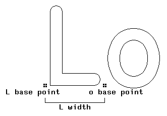
Next, the base point and width should be set for our symbol.
These indicate where symbols are to be positioned
with respect to each other at print time.
Symbols on one print line are placed such that all their base points
are at the same vertical position. The horizontal distance
from the base point of a symbol to the next base point
is given by the width of this symbol.
This is illustrated in the following figure.
 |
The base point of the next symbol is thus always positioned at the current base point plus the current width. To set the base point, choose the Metrics->Set Base command. Position the base point tentatively, with the left mouse button, or with the arrows for single step movements, and fix the position with the middle mouse button. The base point will typically be somewhere near the left bottom corner of a symbol (unless the symbol extends below the base line, like the letter g, or is totally above the base line, like the hyphen).
To set the width of a character, it is convenient to utilize the Typeset Window. Choose the Typeset->New Text command, and type two ampersands ('&&'), followed by the RETURN key. This means: There should be two successive copies of the current character shown next to each other on the Typeset Window.
If no width was set yet, the typeset display will be empty, for the following reasons. Note that the initial width of each character is 1, and the default zoom factor for typesetting curve symbols is 1/5. The width is thus rounded down to zero, i.e., both characters are displayed in the same position. They do thus wipe each other out for the following reason. Characters are placed in the Typeset Window using the Xor operation: Placing a black pixel on a white one or a white pixel on a black one will yield a black pixel. Placing a black pixel on a black one or a white pixel on a white one will yield a white pixel. Placing two identical characters in the same position will cause every black pixel from the first character to get erased by the corresponding black pixel from the second character.
You can now determine the width with the Metrics->Set Width command. This command shows the old width as a dotted line. The new width will be shown as a solid line.
First position the new width (i.e. the solid width line) well beyond the right margin of the symbol, by clicking the left mouse button there. Presently, you will see two distinct copies of the symbol in the Typeset Window, at reduced size (default: one fifth). You can adjust the width by positioning the solid width line with the left mouse button or by performing single step increments/decrements with the left/right arrows. The width is fixed with the middle mouse button.
The curve symbol can now be saved in a font. We first create a new curve font with the File->New Curve Font command. Save the character with the Character->Save Character as command. You will be prompted for a position in the font at which the symbol is to be stored. Hitting A, for instance, will store the symbol in the ASCII position of A (position 65) in the font. At this point, the asterisk next to Char NEW gets erased, because the character has been stored in a font, and NEW gets replaced by 'A' . However, an asterisk will appear next to the font name, NEW_CURVES, indicating that the font was modified and still not saved on disk. The font is saved on disk with the File->Save as command. You are now shown the This can be an arbitrary UNIX file name (including a directory path). Type the file name, followed by pressing the OK button. The font gets saved and the asterisk next to NEW_CURVES disappears.
To quit the TYPO Font Editor, issue the File->Exit command.
To modify a symbol in some already existing font, proceed as follows. If the font is not yet loaded into TYPO work space, load the desired font file with the File->Open command. TYPO determines whether this is a raster or curve font (from the first two characters in the file; see TYPO font formats.
The user is presented with the file selection pop-up window. For starters, just enter the file name into the Selection entry. Clicking OK will cause that file to be loaded.
If some other character does still exist as the current character (i.e. it appears in the Character Window, issue the Character->Close Character command first. (Make sure to save the character first if you have just created or modified it and you want to keep it). Then load the symbol that you want to modify into the Character Window with the Character->Open Character command. You are prompted for the font position of the symbol. Type the ASCII character key of that character position, and the character gets loaded.
You can now modify the symbol, for instance by dragging curve points with the Shift Point Tool, as described above.
To save the modified symbol at its original position in the font, issue the Character->Save Character command. To save the font in the disk file where it was loaded from, issue the File->Save command.
You can paint black pixels with the Pencil Tool. After the tool is chosen, pixels are painted while dragging the mouse. Releasing the left mouse button will stop painting. To draw a black line, use the Line Pencil Tool; there, a rubber band from the start point to the tentative end point will be shown while you drag the mouse. To paint white pixels, use the Eraser Tool.
Determine the base point and width with the Metrics->Set Base and Metrics->Set Width commands, as described above for curve characters.
Save the symbol with the Character->Save Character as command, and then create and save the font with File->New Raster Font and File->Save as, just like described above for curve characters.